Home The Donor Tear Down Engine Transmission Rear End Wiring
Cooling A/C Fuel Exhaust Links Brakes
Wiring. How hard can it be? After all, I have quite a bit of wiring experience on the planes Ive built. But alas, it was certainly the most difficult part of the job. Part of it was my own fault dealing with these salvage yards. They just dont know what they are doing. When you get your engine, you need the pedal, throttle control module, and the wiring harness.
My CTS-V LS6 fly by wire engine had plenty of wires to deal with. The most important item are the diagrams. Please see the link sections for diagrams.
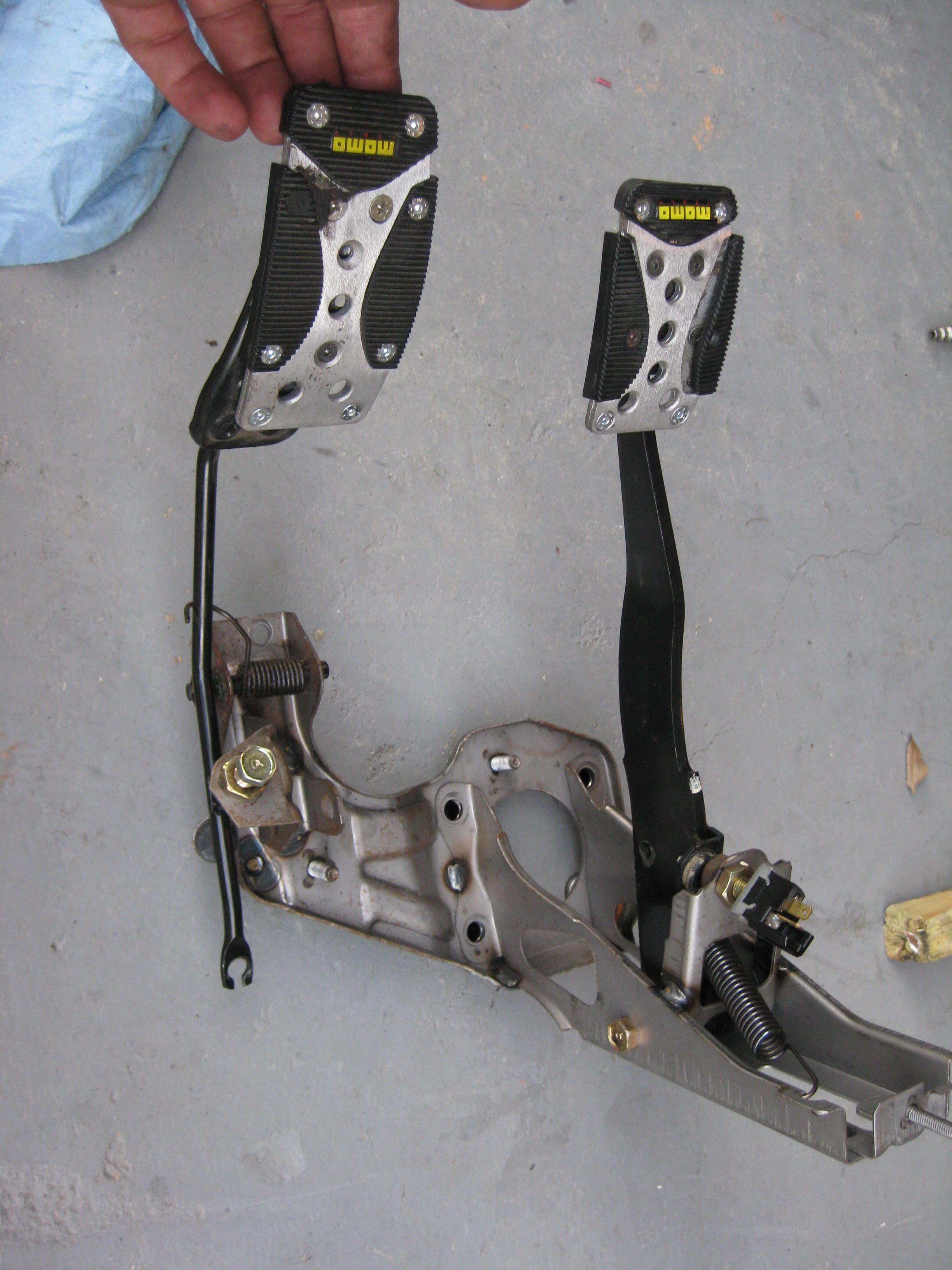
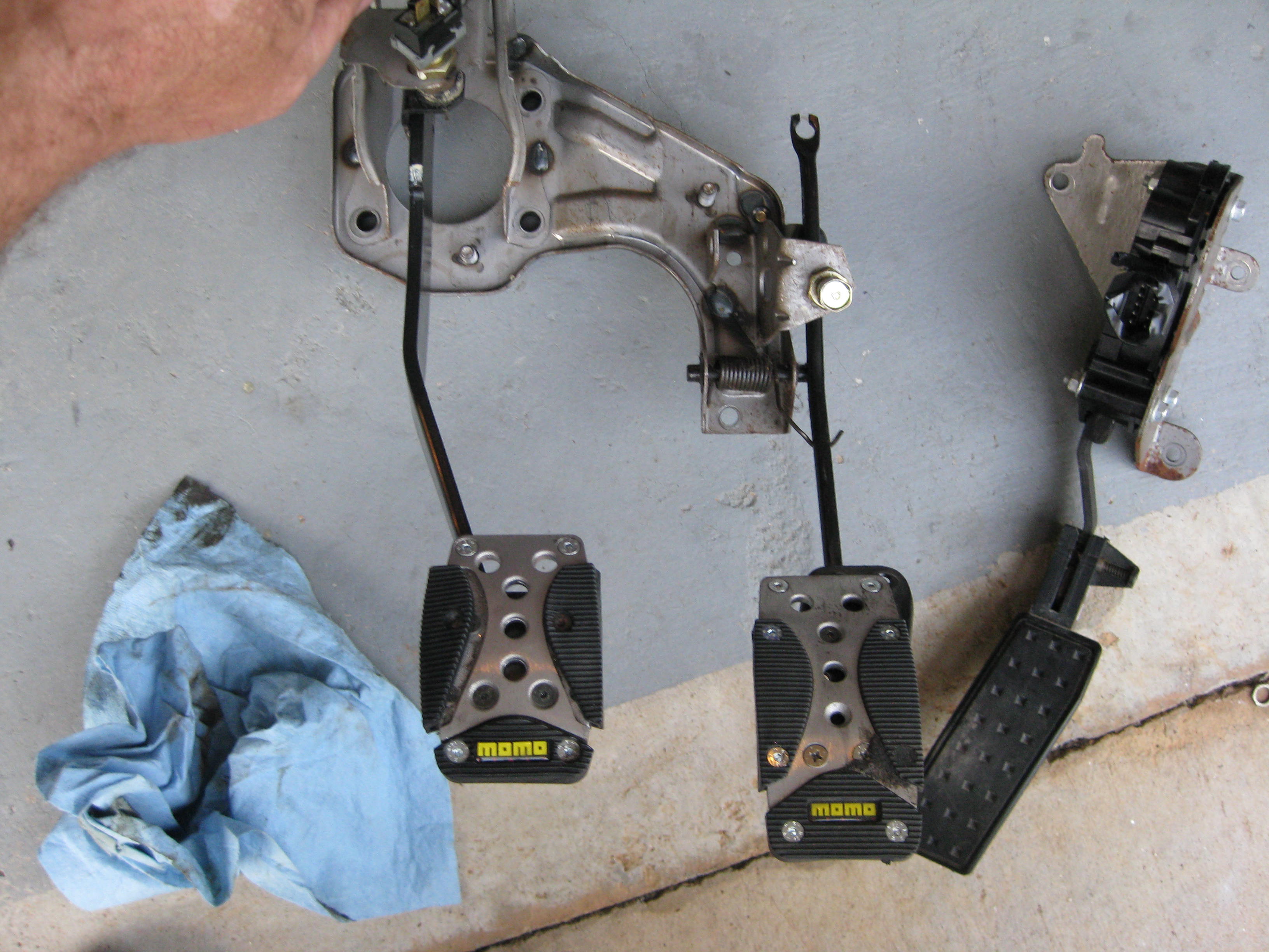
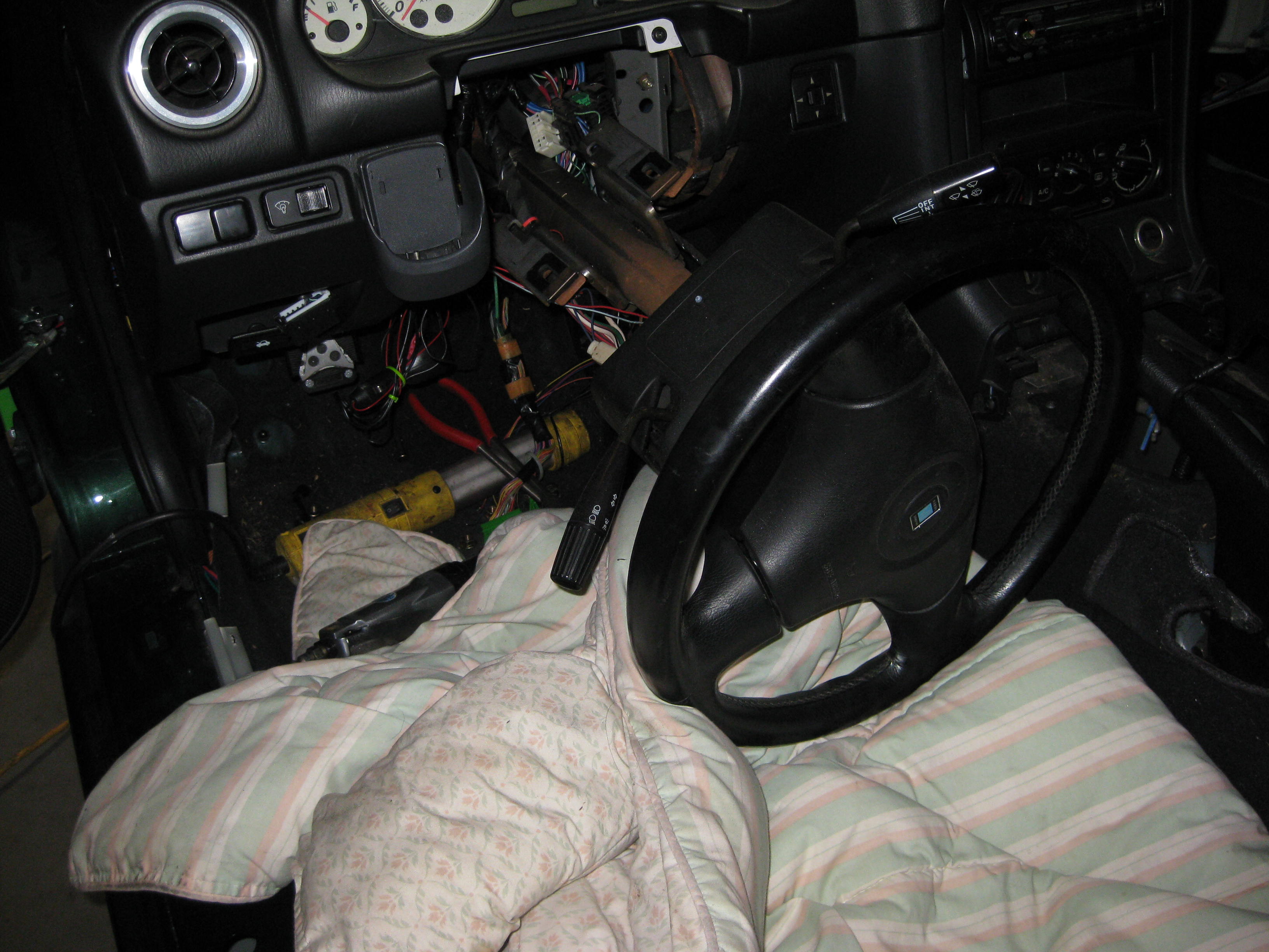
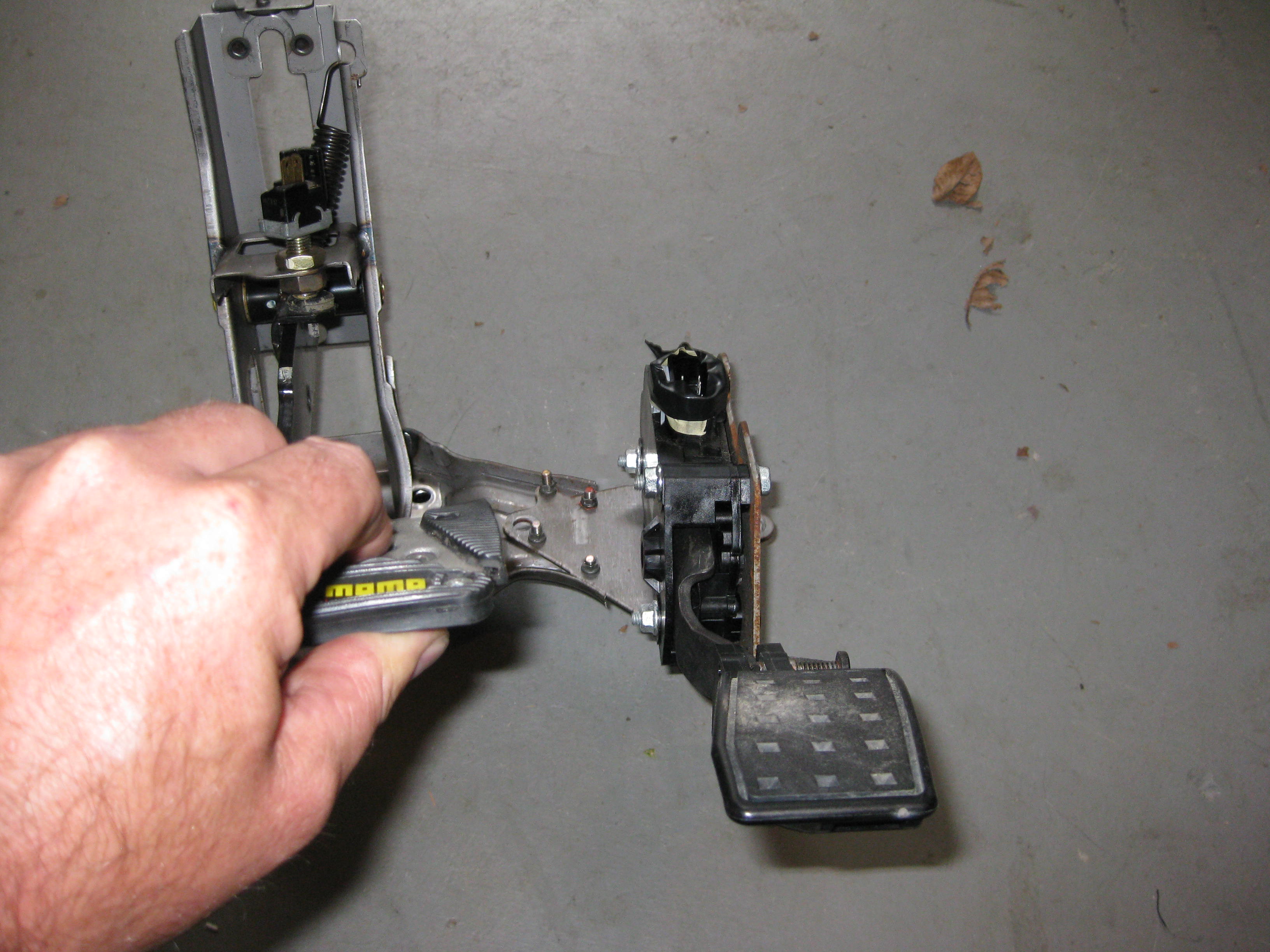
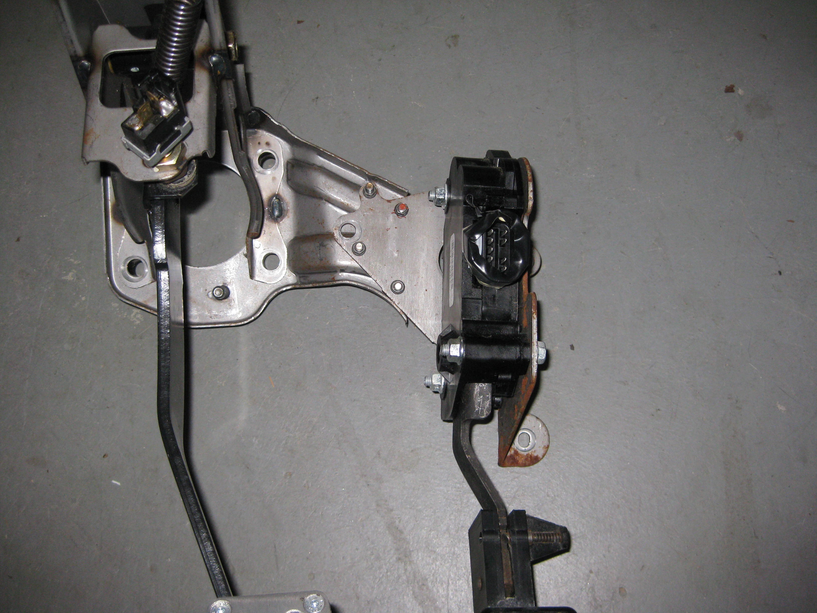
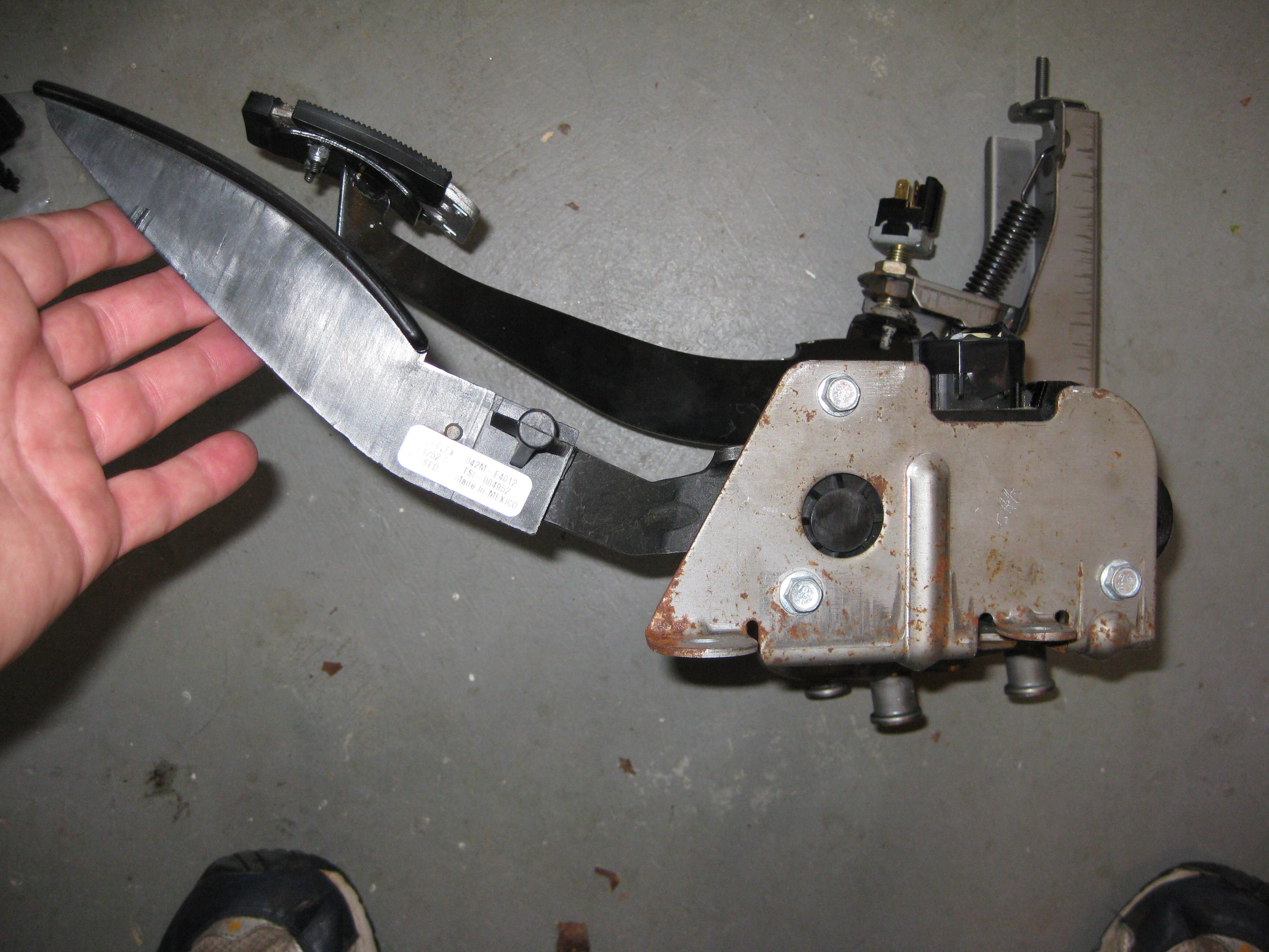
First item it the fly by wire gas accelerator pedal. Mine came off an 03 GMC Sierra. I took a few pictures. The pedal assembly must be removed. This requires dropping the steering column.
I used some bolts and she fit right in. Here are some fitting pictures.
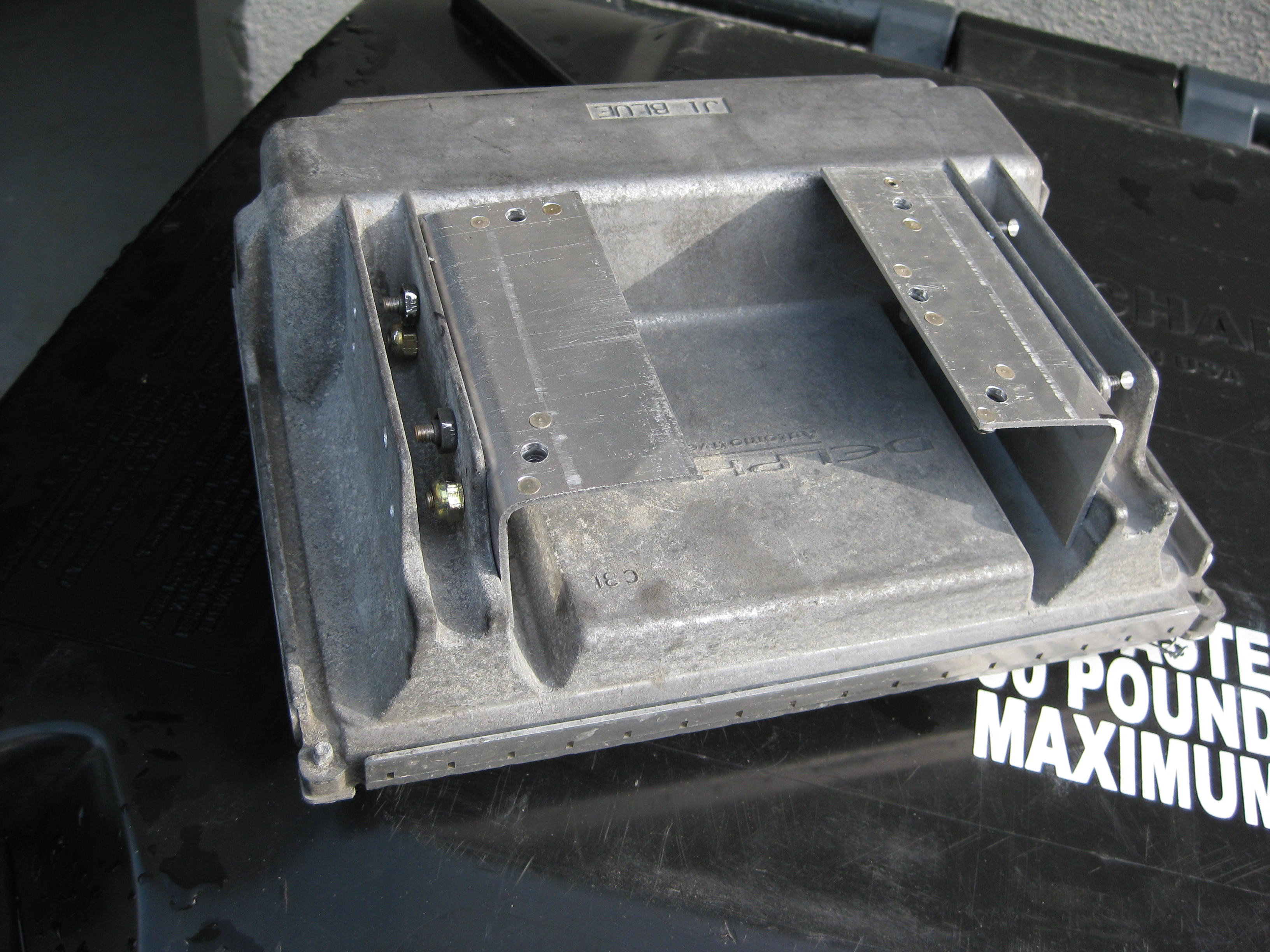
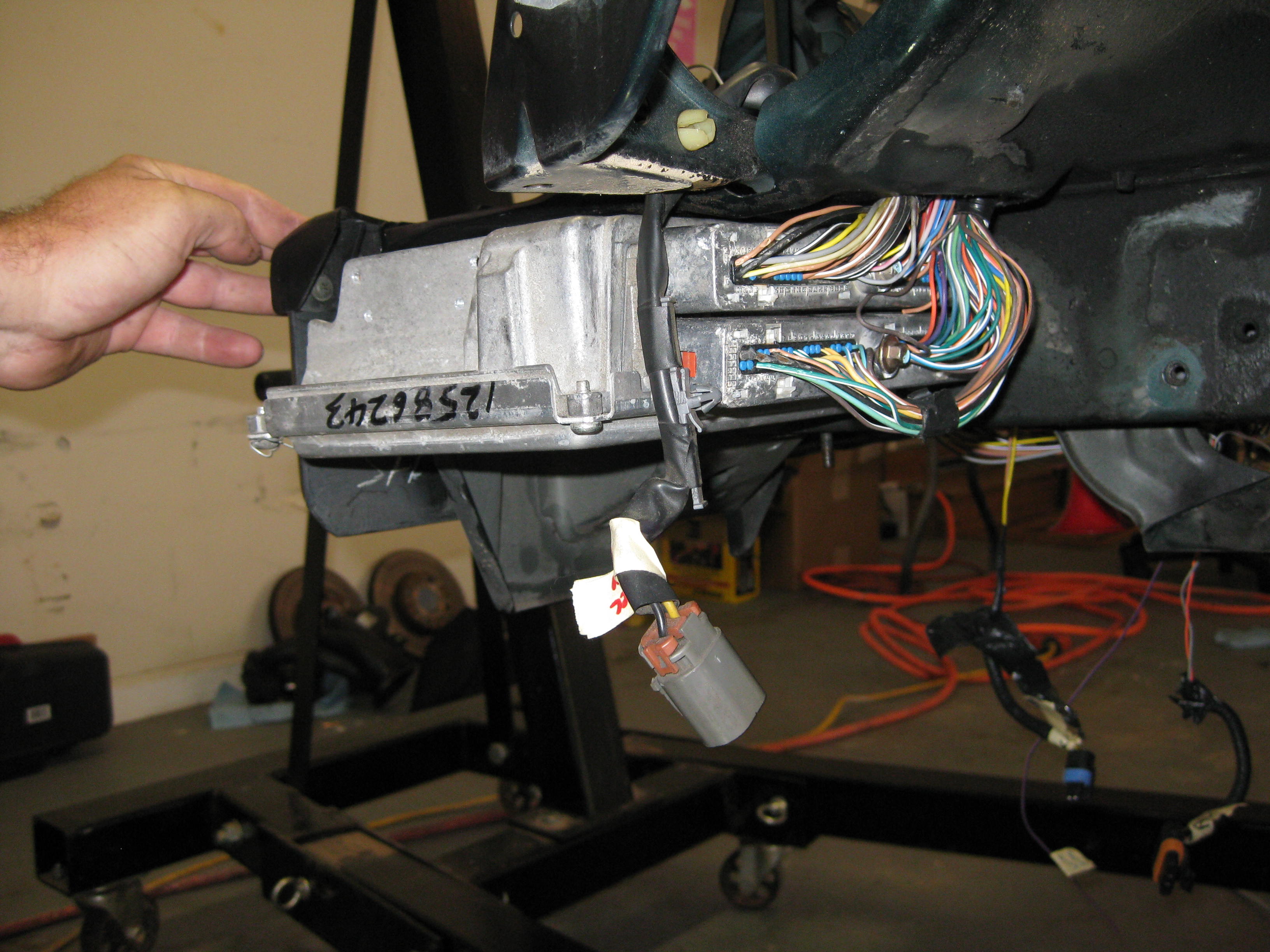
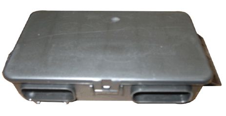
Another item is the ECU, or the engine computer. Mine was smashed up in the wreck from the salvage, I ordered one from Anthony/Alex. $185 tune + $15 shipping (your ECM, if you need an ECM, it is $75 extra). Its required that you get your PCM programmed. Items like CATS, O2 sensors, VAT (vehicle anti-theft) and so forth need to be ripped outta there.
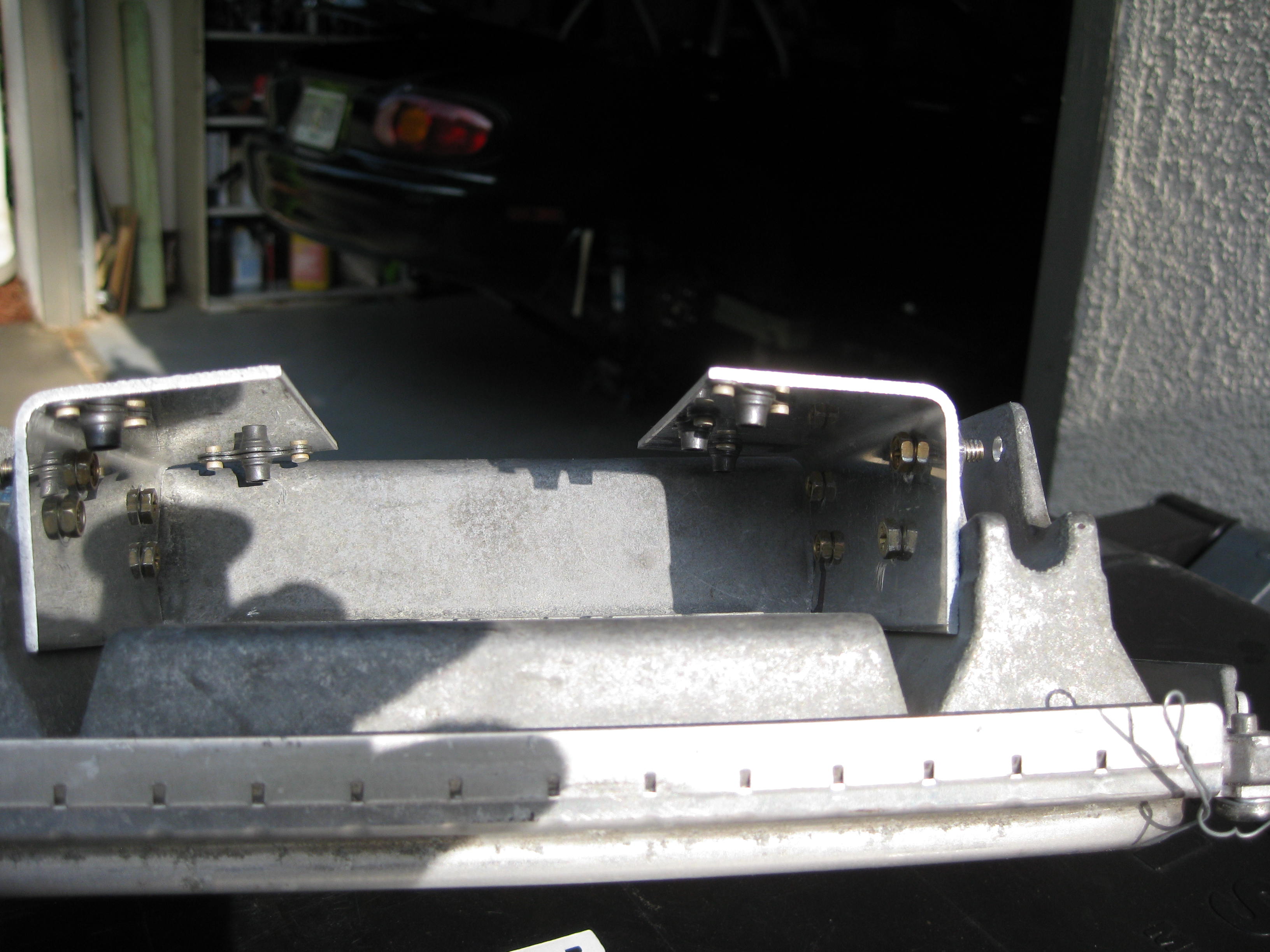
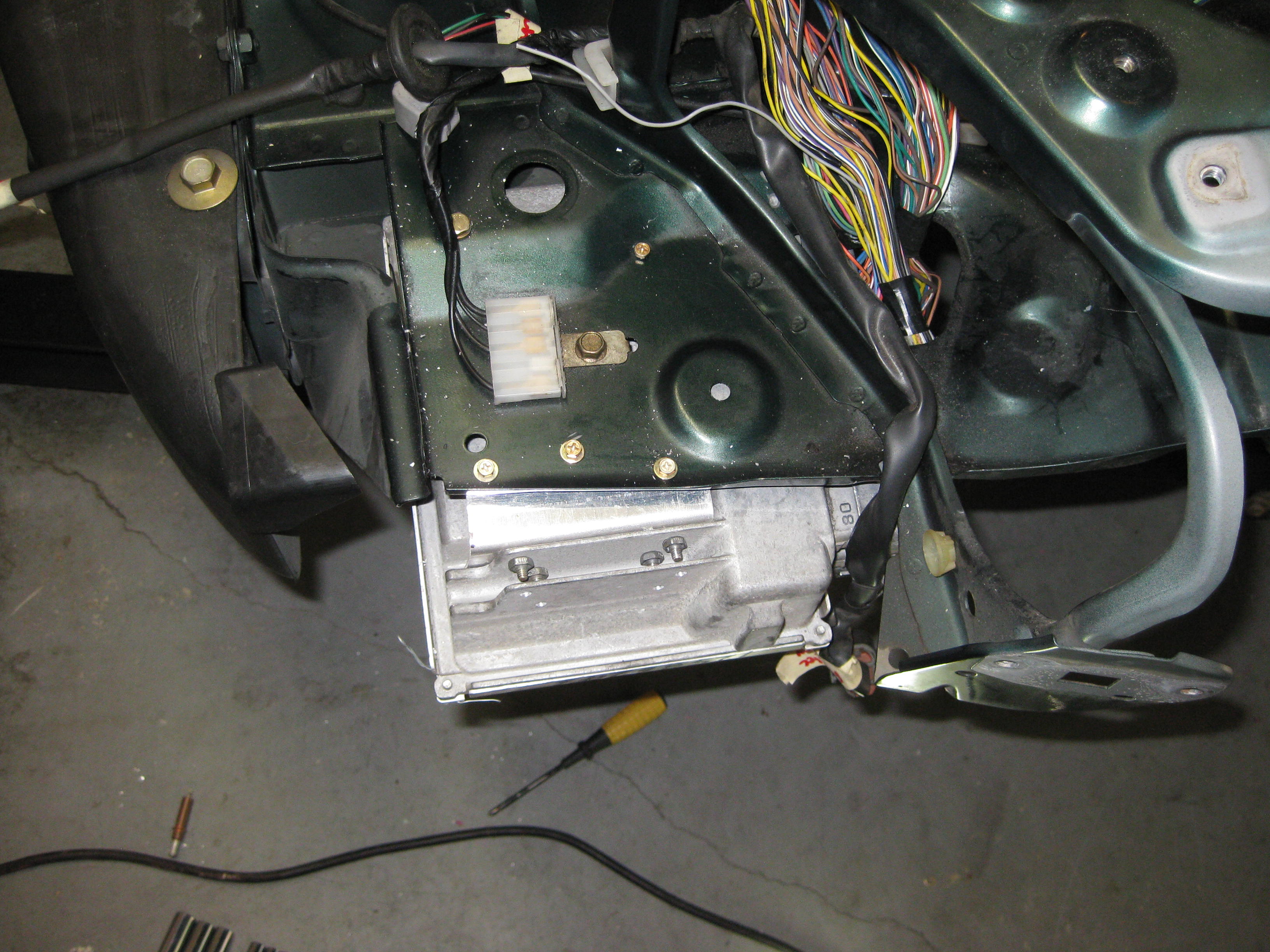
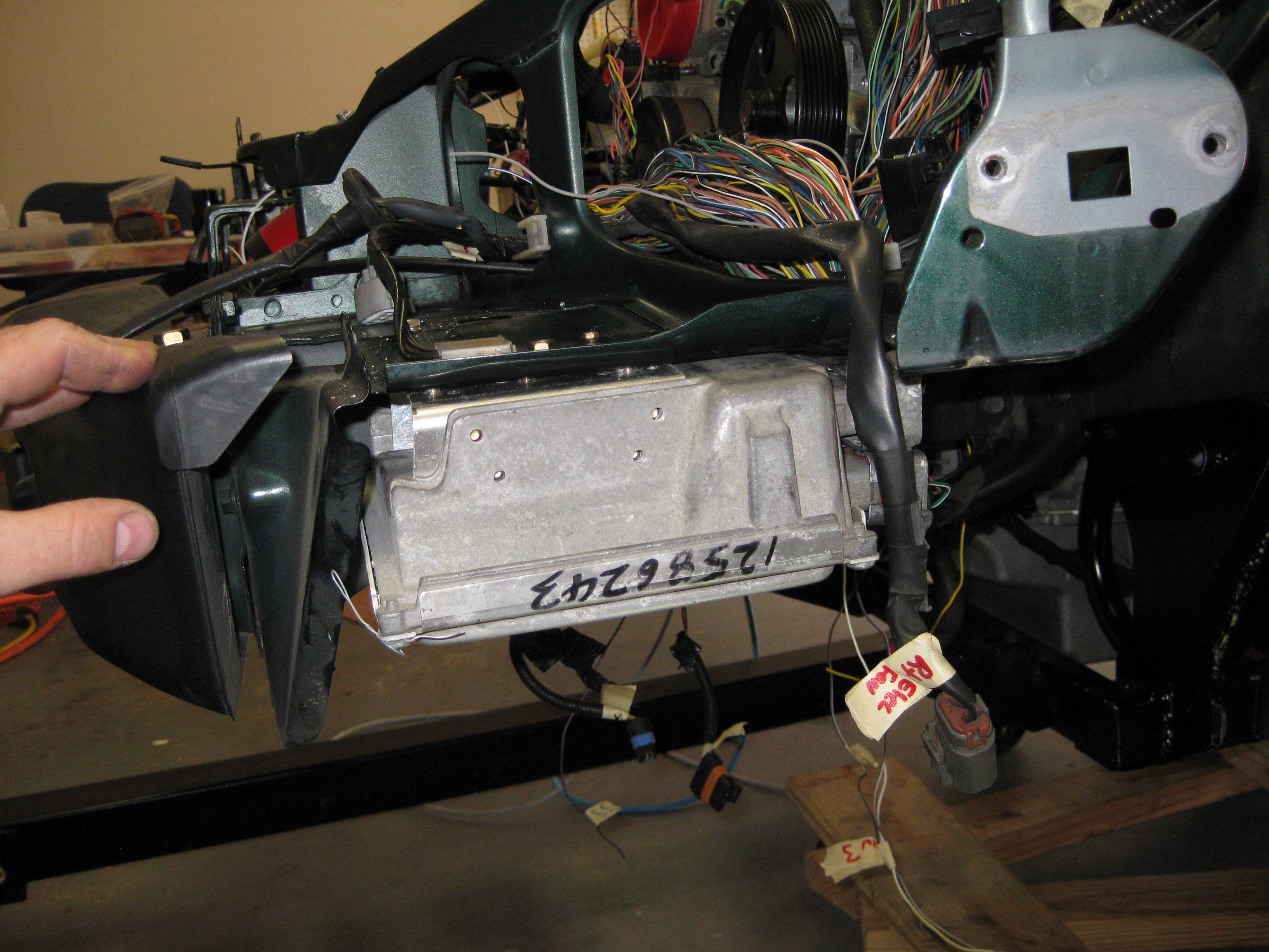
Location is a problem. This monstrous thing has no business under the hood. I jsut could not stomach that ugly thing in my engine compartment. So I located it in the left wheel area. I used some aluminum aircraft angle, some platenuts, and a few nuts and bolts.
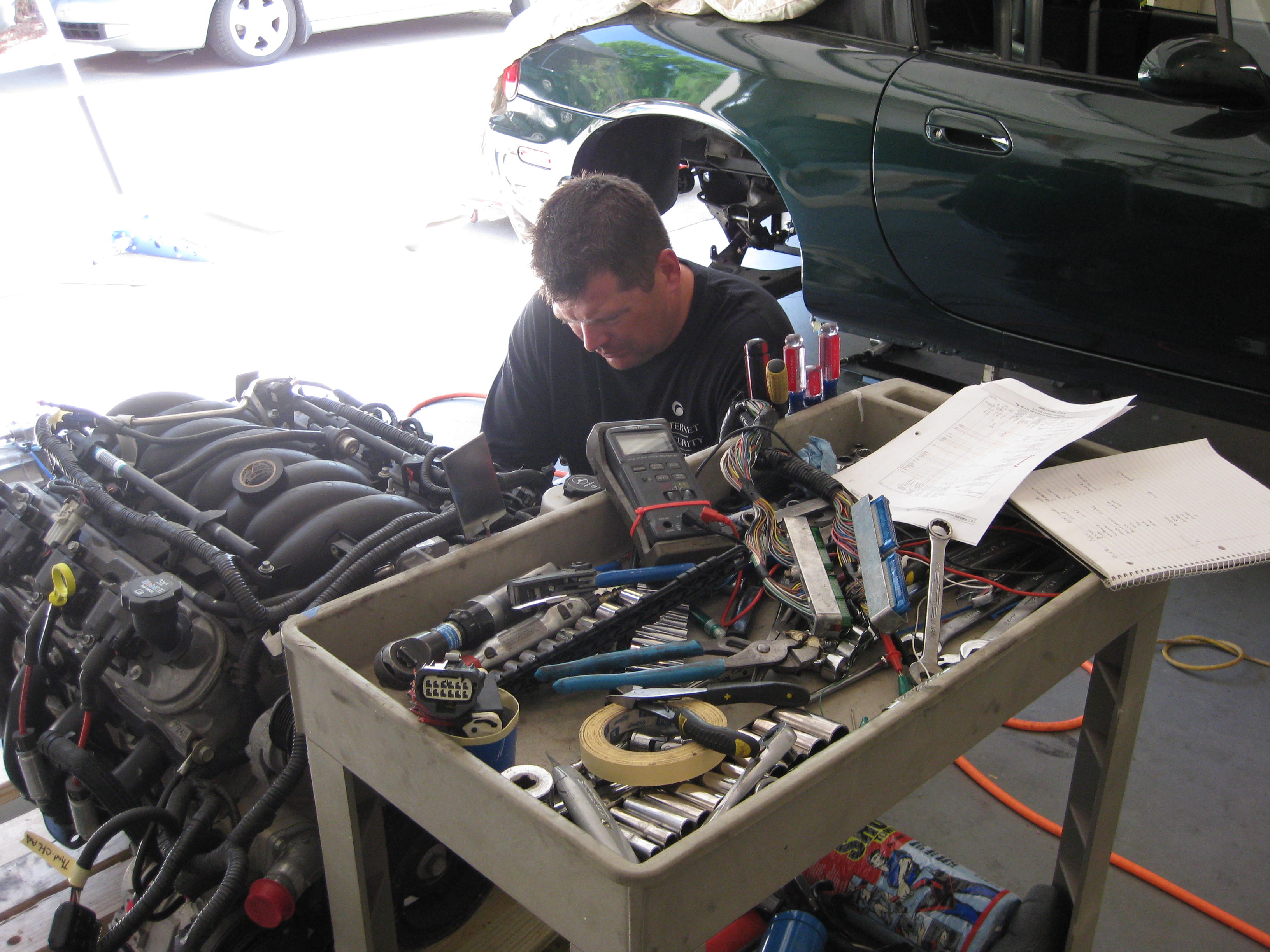
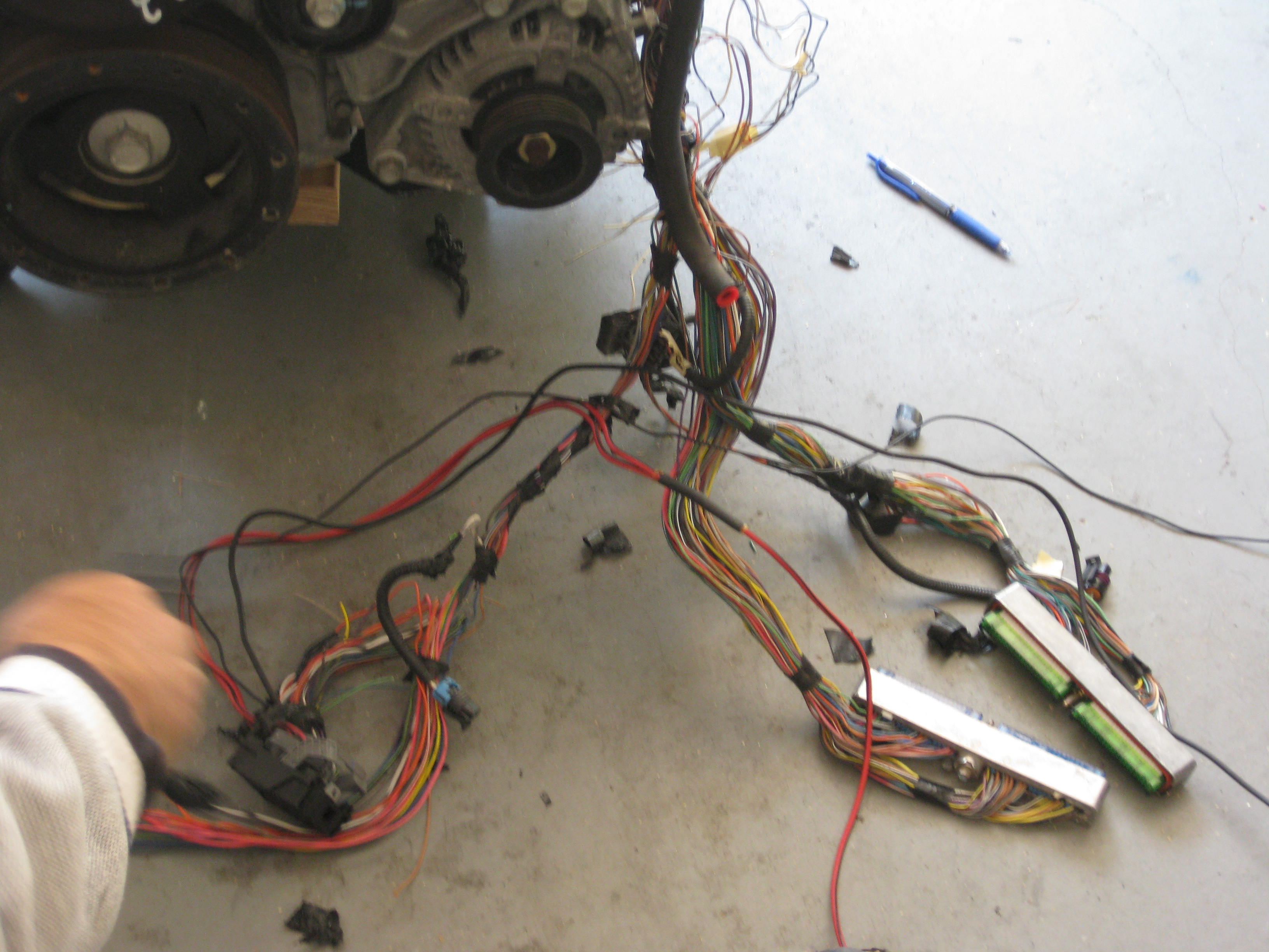
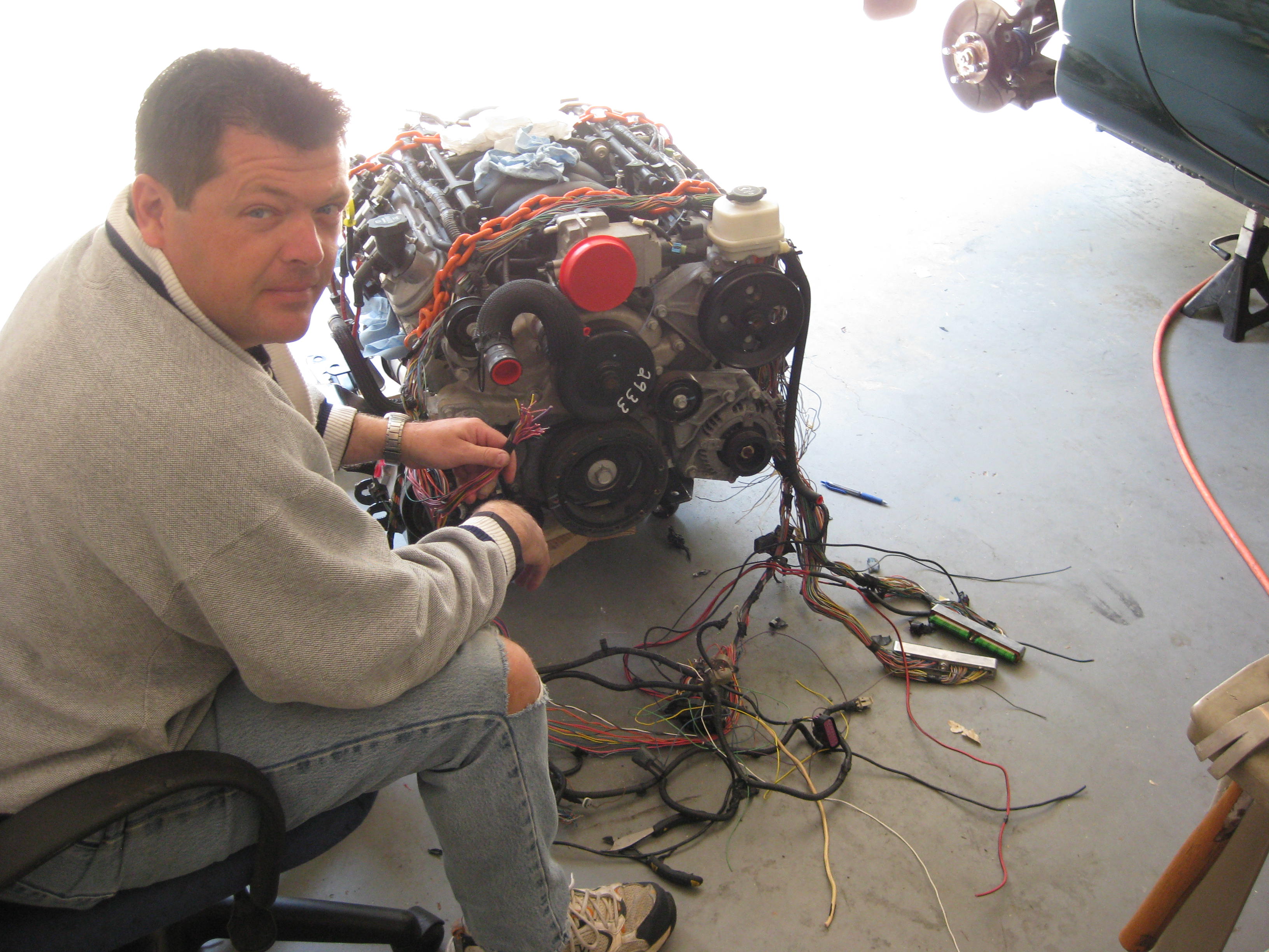
Wiring.... Where to start. The first place is to pull apart the harness, leaving the parts at the injection rails and the transmission. You must know where every connector goes, verify pins through the wiring diagrams, and know what every wire and connector does. This takes time, patience and a willingness to learn.
First, pull the plastic off. Get comfortable, get out the wiring diagrams, and start checking colors, continuity, and bundles. I had ~10 connectors going to my transmission. But none had been connected to THIS transmission. So I had to figure out what each one did. I marked em with masking tape and wrote everything down. Pages of items. I sat on the floor, and just traced each wire. This took a few after work nights to trace down. Then its a matter of figuring out what needs mating to the Miata.


This is the Miata relay deck right rear under the hood. I marked each connector. I wrote down everything I did. Wesley worked on the frame rails.

Below is information for my records that you might find useful.
15pin Molex I built. The PCM has 2 big connectors. One Blue and One Green. B54 referrs to Blue connector Pin 54.
| Molex Pin | Purpose | PCM Pin | Comment |
| 1 | +12 unsw | B20&B57 | Picked up +12unsw from the cooling fan relay rt rear engine compartment Bl/Y |
| 2 | +12 sw | All the pink and Pink black wires | There were a bunch so I ran en through 3 pins to spread the love |
| 3 | +12 sw | All the pink and Pink black wires | There were a bunch so I ran en through 3 pins to spread the love |
| 4 | +12 sw | All the pink and Pink black wires | There were a bunch so I ran en through 3 pins to spread the love |
| 5 | relay Coil Ctl | B39 | may use later |
| 6 | Eng Cooling fan relay ctl | B42 | May use later |
| 7 | High speed A/C relay clutch ctl | ??? | May use later |
| 8 | To A/C clutch | n/a | Activate A/C clutch. May use later |
| 9 | A/C clutch relay | G43 | May use later |
| 10 | Main Relay ctl | G65 | May use later |
| 11 | Speedo Out | G50 | through my grey cable to cluster Yel wire |
| 12 | to B/U sw | NA | not used. Disregard |
| 13 | Fuel Pump Relay Ctl | G9 Grn/Wh | through my grey cable Grn wire to driver side relay> See relay rewires below |
| 14 | Tach out | G10 | through my grey cable Or wire to cluster Gr/Or |
| 15 | unused |
Miata water temp sensor.
You can screw your Miata water temp sensor into the top right rear of the engine, above the header. Remove allen, insert sensor. My connector went with my old engine. So I used push ons, pro-sealed em in, and wired to existing gage wires with a molex inbetween.
Looking at the sensor, triangle down, tab up.
1 2
3
1 = Blk/Red runs to Orange wire in my bundle to Molex pin 3
2 = Red/Bl runs to Grey wire in my bundle to molex pin 3
3 = PPL/Wh runs to yellow runs to Molex pin 3.
I used small push on tabs, crimp type, and some proseal (stuff we use to seal aircraft fuel tanks with), but red rtv would work.

LS6 Alternator.
Good news here. Fat wire to the starter already. Small wires to the PCM harness already. Yipee!.
2 wires at the alternator. Or=G15=Alt. Term L, Gry=G75=Alternator Duty Signal
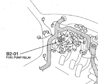
Fuel pump relay. Miata fuel pump relay supplies ground to activate. GM supplies +12. Here's how to swap it around. Locate the FP relay under the panel.
Wires stock are as follows.
Wh/Bl = +12 coil
LtGrn = gnd, sw by ECU
Wht/Bl = +12 supply
Red/Bl = +12 output to pump
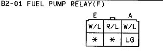
Take the Lt gren wire, cut it, run it from relay to ground near by
Take the Wht/Bl wire, cut it, run it from your relay to your G9 wire and your done.
Fly By Wire Throttle
The LS6 is a fly by wire system. There is a throttle pedal, a throttle control module, a throttle actuator servo at the throttle body, and the PCM that ties it together. Make sure you get the throttle and TAC( Throttle Actuator Module) with your engine along with the connectors to em.
Pedal Here
GM Replacement "TAC" Module
(Throttle Actuator Control) For Drive By Wire Applications 12578953
Original Replacement For 1997-2004 Corvette & 2004-2005 Cadillac CTS & STS. This
box integrates your pedal, throttle servo, and PCM. There are 2 connectors.
Now for the biggest challenge that cost me 2 weeks of effort, head scratching, and wasted time. When I bought my engine, I got the harness, and not the TAC. The pedal connector was cut 6" pigtails. So off I went and bought a new $400 TAC. Wired it up per the diagram below. The DIAGRAM WAS WRONG! Its says A to A pin, B to B pin and so forth. Seems easy enough right? This snip picture below is from the Mitchel diagram.
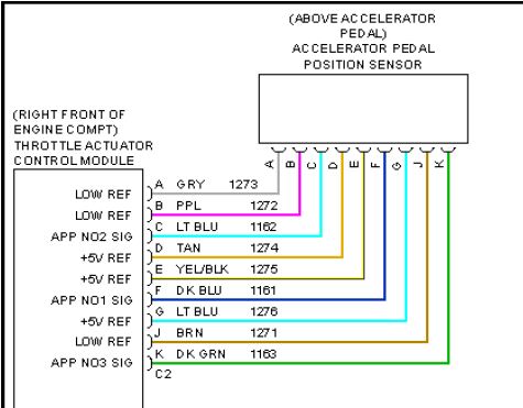
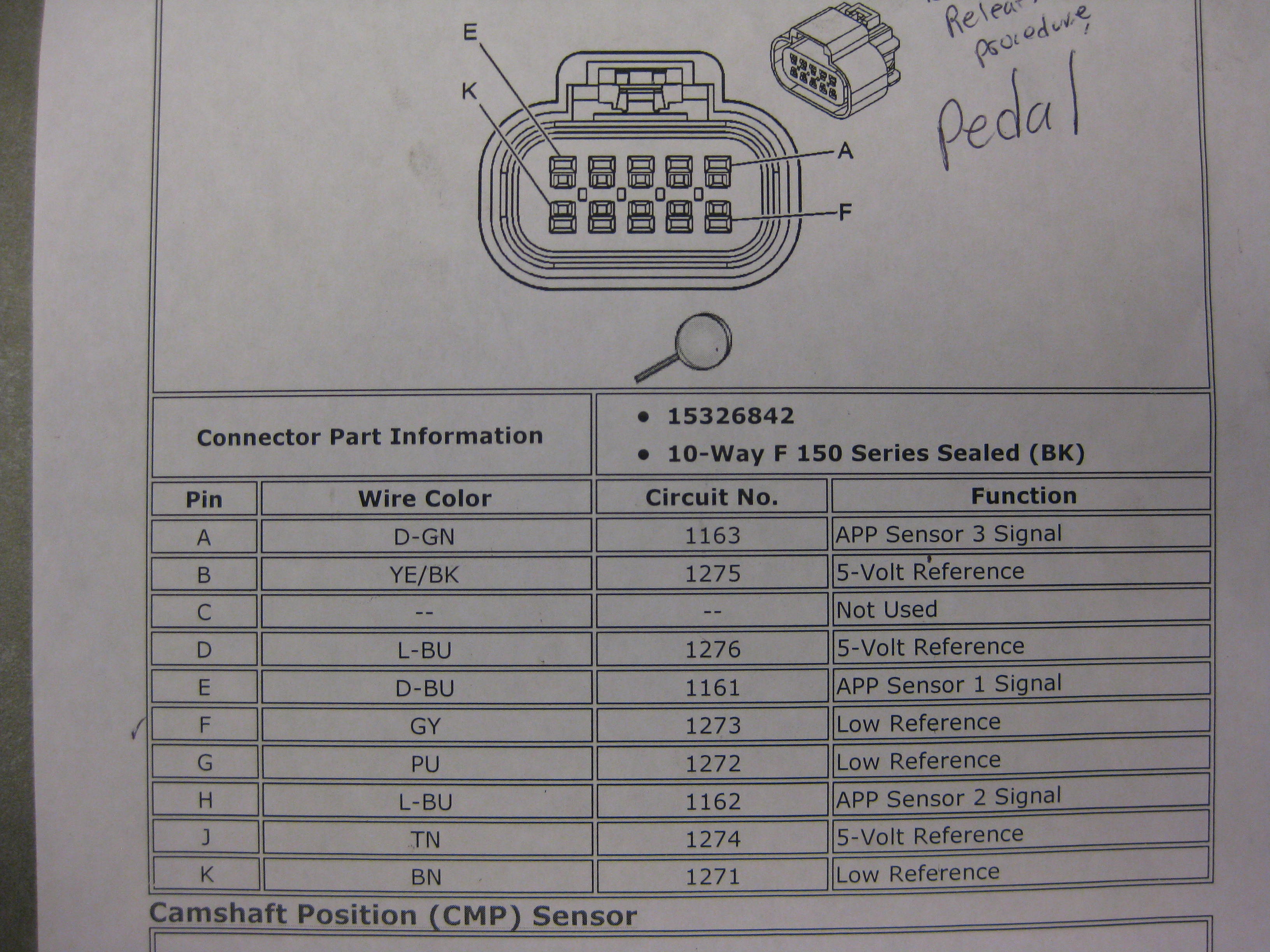
After the new TAC would also not operate the throttle, I went to buy a new pedal. While at the dealership, a great GM technician allowed me to view and print the wiring diagram for the Pedal and TAC. To my shock, the wiring on his GM data was completely different than mine. ARRGH!!. Here is a shot of the pedal connector from GM database. You will notice pin A on the pedal is DkGrn, NOT grey like the one out of the Mitchell. These 2 shots of the diagram below clearly show that pin A from the TAC does not go to PIN A from the pedal. ARGH! The cost me time and money and a lot of frustration. Once I hooked it up per the GM pinouts, wallah, it worked.

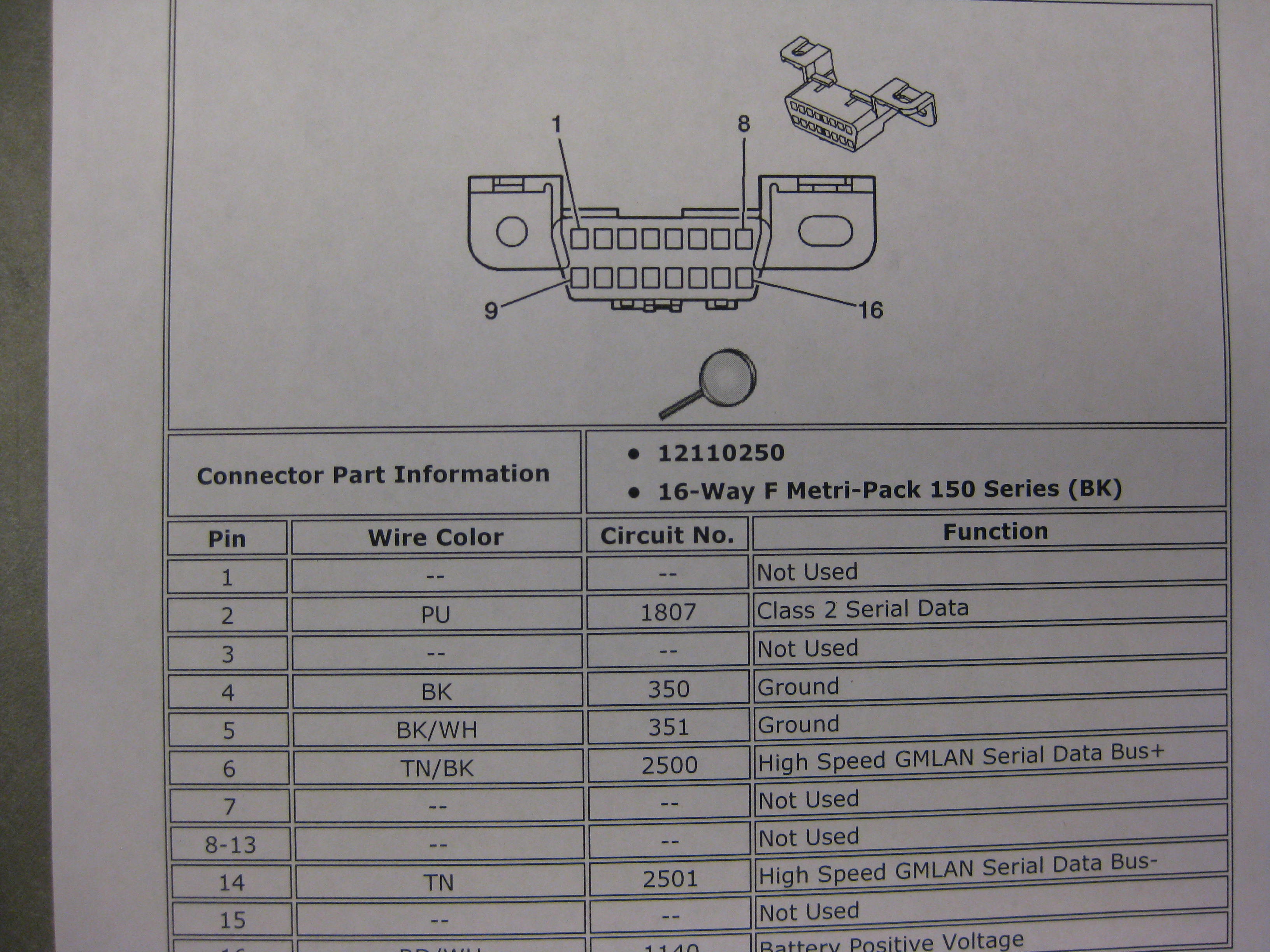
OBDII Wiring
You can interface your OBD II connector to your new PCM.
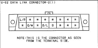
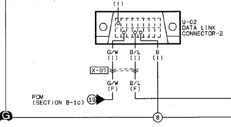
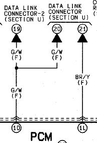
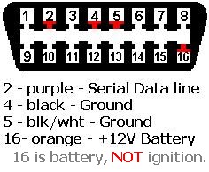
Here are a couple shots of the connector pins in the Miata, or any other OBDII for that matter. Pay close attention to the connector orientation. I spent at least a day trying to figure out why I could not talk to the computer through the DLC (Data Link Connector). What threw me off was that the Miata Gr/Wt wire on the DLC is on pin 7 and makes it look like its on pin 2. See Miata diagrams below. Night after night I trouble shot and came to the same conclusion. it doesnt work!! Well I was wrong. It does work IF you move the gr/wt wire from pin 7 to pin 2. Connect the gr/wh wire to your PCM on 58 or 59, and your good to go. Geez! What a pain.
12 Pin connector at Engine. Pedal Pin Out for my personal wiring history. This is Pedal to TAC (Throttle Actuator Control Module) Descritpion above.
Pig tails out of the pedal are wired to a blue cable I installed to a moles connector rt side eng compartment, to the TAC.
| Pedal Connector Pin | Color Wire AT Pedal | Blue cable enroute to Engine compartment | TAC Pin | 12 pin Molex Connector Eng compartment |
| A | DkGrn | Gr\Bk | K | 1 |
| B | Y/Bk | Red/Bk | E | 2 |
| C | - | - | - | |
| D | LtBl | Grn | G | 4 |
| E | Bl | Bl\Bk | F | 5 |
| F | LtGry | Wht | A | 6 |
| G | PPL | Bk\Wh | B | 7 |
| H | LtBl | Grn | C | 8 |
| I | Tan | Wh\Bk | D | 9 |
| J | Brn | Brn | J | 10 |
9 Pin Molex I installed to connect PCM into drivers side wire bundle.
Pin 1, from PCM B58 Serial PPL, through blue cable Bl wire, thru firewall, exits near pedal, changes to Grn. to DLC OBD pin 2
Pin 2, from PCM B59 Serial PPL, through blue cable Or wire, thru firewall, exits near pedal, changes to Red. Not used for now.
Pin 12, From PCM G46 MIL Lt, through grey cable Wht wire thru firewall, to the instrument cluster Wht\Bl wire
Heated O2 Sensors.
The LS6 PCM is looking for 4 heated O2 sensors. 2 per side. One before the cats, one after. I had them remove the rear ones from the PCM programming. That left 2 to wire.
The Miata is equipped with 2 O2 sensors. One before and one after the Cats. The LS6 harness has 2 connectors near the top right and left of the bell housing. One goes to the left O2, one to the right.
I cut the miata rear O2 sensor and used it to wire in to the front. Here is the wiring to my 4 pin moles connectors. One left and one right. I cut the LS6 connectors off. Mated the wires to the Miata O2 sensors via molex.
| Left Front O2 LS6 wire Color | Miata O2 Wire Color | LS6 Rt, Front Wire color | Purpose |
| Pink\Bk | Blk | Pink/Bk | Heater+12 |
| Grey\Wht | Blk | Lt. Grn | Heater Gnd |
| PPL/Wh | Blue | PPL | Signal |
| Tan | Wht | Tan | Signal gnd |
Getting the Tachometer to work
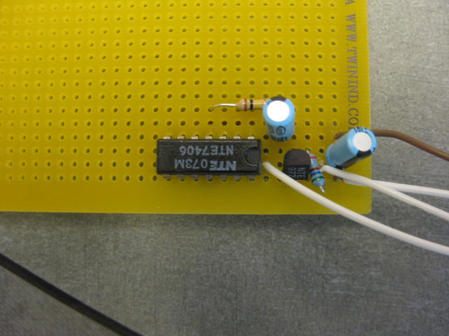
I tried simply hooking up the PCM tach out G50 wire directly to the cluster Grn/Or. No joy. Needle didnt budge. A perusing of the LS1tech forums found this issue to be common. I needed a pull-up circuit. Some guys got away with simply installing a 10k-13k getting to the 12v square wave that the tach is looking for. One guy thought he cooked his PCM using the resistor only method. I dunno. I took the safe route and built a tach signal conditioner. Interesting threads on it here, here, . I tried the 13k resistor pull up method. Tach moved fine, but saw erratic behavior. Also saw my speedo jump up while rev'g in neutral. So I installed this board below and it works just fine. I found +12 and gnd at the cluster and tapped off them to support this setup.
Parts from Fryes electronics ~$13
7100-45 bread board
1/4w 560 resistor pack #1005063
1/4w 100ohm resistor pack # 1004983
10 MFD capacitor #1709777
Voltage regulator NTE +5v 3 terminal #1975525
IC inverter buffer NTE 7406 #1003353
Here is a shot of the board before cutting it.