Many folks with the 6cyl Lycoming complain of an annoying vibration in the airframe when flown in conjunction with the Hartzell 2 blade prop. I had this vibration and its one that has annoyed me from day one. I have an IO-540 C4B5 260hp, Single LSE electronic ignition. My hub is a HC-C2YR-1B and my blades are F-8465-7R
After the first 50 hours of flying, I found the vibration to be excessive and through conversations with Hartzell's Les Doud, and Lord mounts, we came up with a possible solution to change from the Vans part number VIP50011-20 MFG 15332 made by Vibration Isolator Products, to the Lord J-9613-12. This made a great improvement. After several dynamic balances by 3 different individuals, and after ~400 hours of flying, I decided to track down the rest of the vibration AFTER i went out and bought an MT 3 blade. You can read about that here.
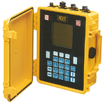
First step is to really measure the vibration, not just my butt feel. Doug Ripley, good friend and builder extraordinaire, lent me his ACES model 2015 prop balancer. This device also has the ability to measure the full spectrum of vibrations and frequencies. Next, I got in contact again with Les Doud at Hartzell. Les immediately jumped in the fray with me to begin pointing me in the right direction of exactly how to capture data in such a way as he could interpret it.
Clamp the transducer in the cockpit with the transducer vertical, go fly at a series of RPM's at a fixed manifold pressure, and capture the data. Here is the gismo capturing the data and a pic of the mounted transducer.
![]()
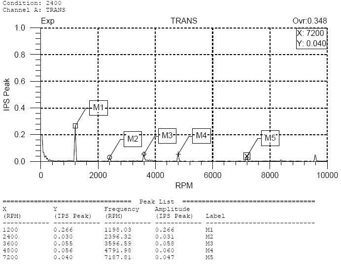
I went to ~7k', 23.3"MP, lean to 75ROP, and capture data at 2600, 2400, 2200, 2000 rpm. All of the data can be found here. This is a snapshot of what you get out of the unit in combination with their software. Here is a view of 2400RPM. What you see is a 1/2 order harmonic. Meaning that at 2400 RPM, there is a vibration at 1200RPM who's amplitude is .266 IPS(Inch/sec). See the M1 callout.
What's cool about this is that its not just my butt feel, now I got real data. As Les put it, "we have now calibrated your butt." So with this data in hand, Les had a theory. Lets change the prop clocking position and see if we can make improvement on this 1/2 order vibration. So with that I began to reclock the prop and this is a whole nuther saga. Ill give you the short version.
The prop hub has 6 holes, 4 of the have counter bores in them to accept the crank flange bushings that extend past the ring gear and go into the prop hub. This allows the prop to be in one position, or 180degrees the other. If your crank is @ #1cyl TDC, your blades would be in the 1-7 o-clock position. In order to move the prop to the proposed 9-3 position, one of 2 things has to take place. Either move the bushings in the crank flange, or counter bore holes in the prop hub to accept the bushings without moving them. I decided to try moving the bushings. Lycoming has a Service bulletin on this. I have an IO-540-C4B5 Figure 2, .38 flange. This meant that I would need 2 bushings, a 72061-S and a 72074-S. So with bushings in hand I attempted to remove them. After futzing with it for the better part of a day, I decided that I was going to tear something up. I did not have on hand the special removal tool. I had a rig that I expected to work, but it didnt. So I went to plan B.
Plan B is to counter bore the 2 holes in the prop hub that do not currently have them. Warning: This is not a recommended procedure by anyone at Hartzell. Boring holes in your prop hub is something to take very seriously and is not condoned by anyone, including me! Don't try this at home. Read this disclaimer.In fact, I was warned against it by Les and others. As my momma used to say "son you don't listen too well." I evaluated the risks, and pressed on.
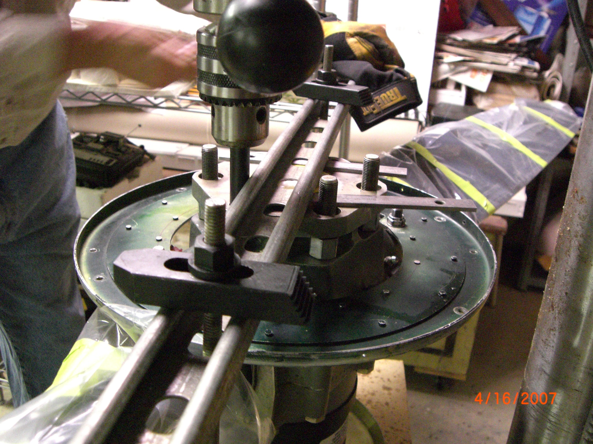
Now on to what I did as an experiment that I don't recommend you do. What I liked about this solution is that with all holes in the prop hub counter bored to accept the long bushings, I could clock the prop in any position. So I called my machinist friend David Posey on a Sunday morning and headed off to his place for the job with my prop.
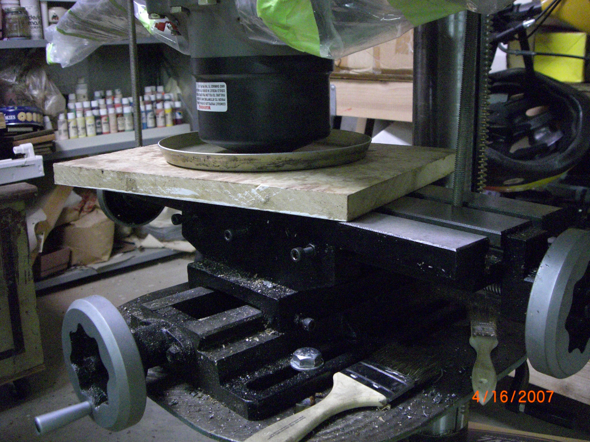
We mounted the prop in a drill press and jigged it all up. He had guide pins and other items I thought were pretty cool to get this job done. I learned a lot.
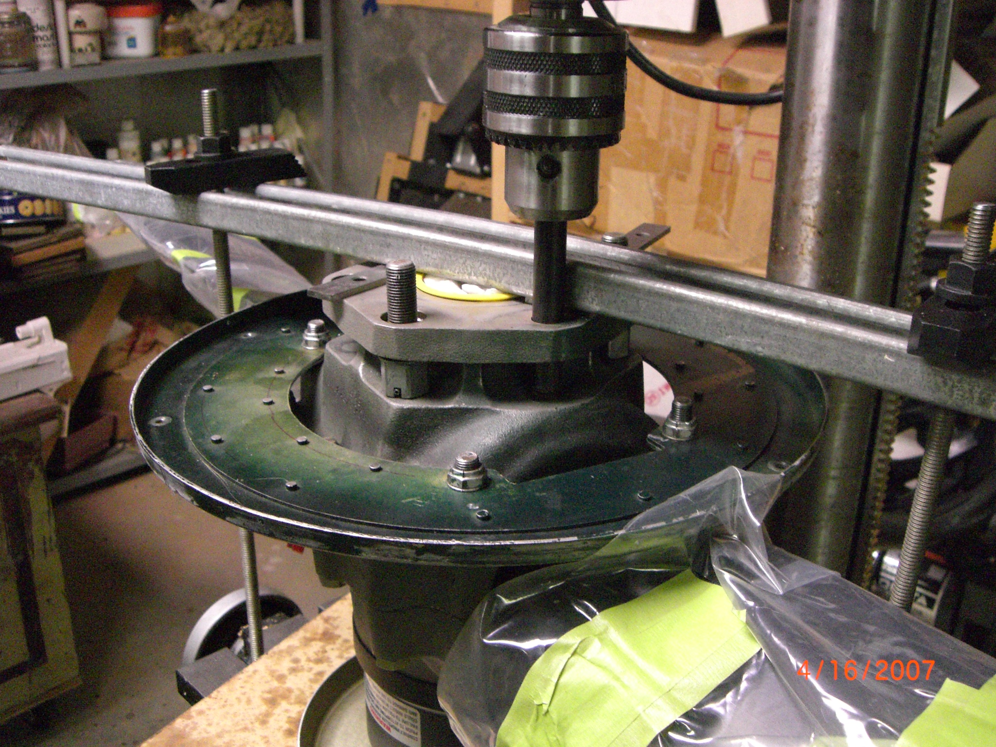
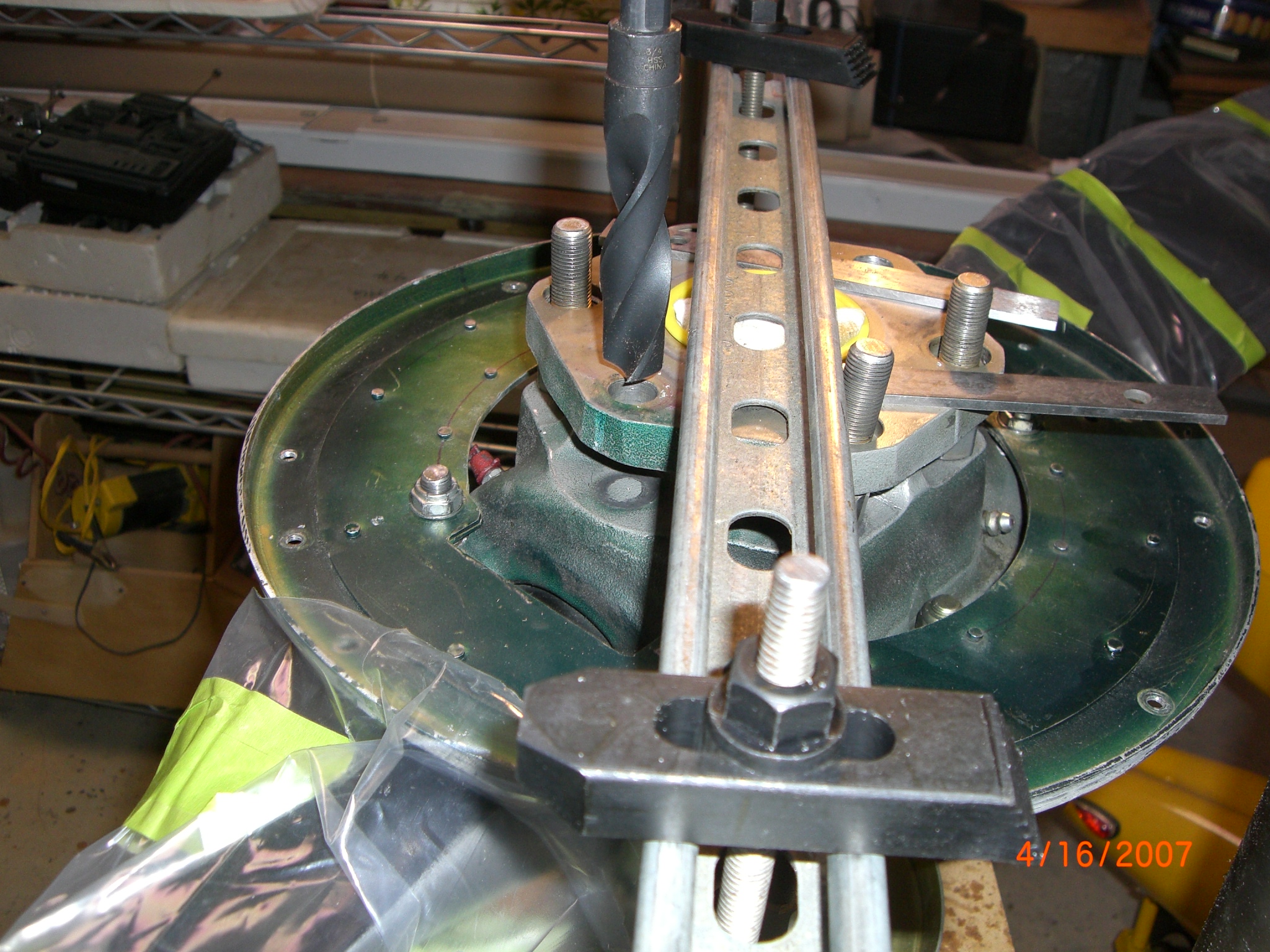
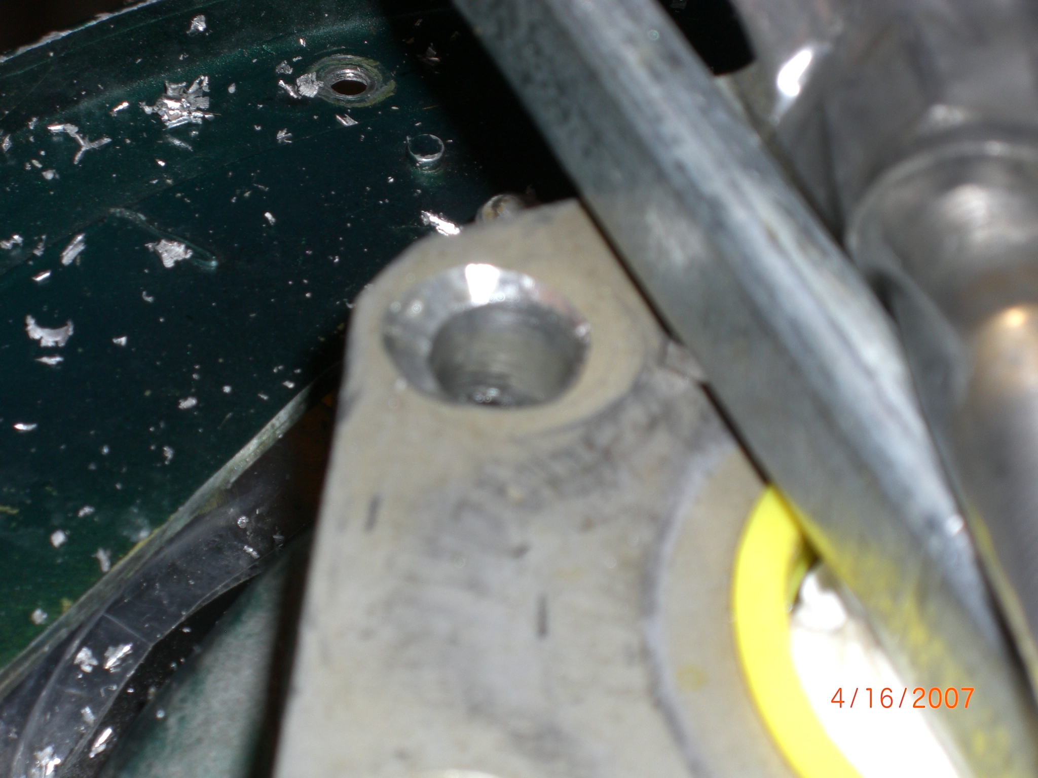
The first hole went fine, the second hole though, did not. As we began drilling, the hole, the prop began to chatter and the drill began going off center. AHHHH!!!!! Crap. Dang. Sh!@#. Here is a blurry picture
OK Stop everything. We need a counter boring bit. So it was off to McMaster Carr to get the correct bit. And here it is.

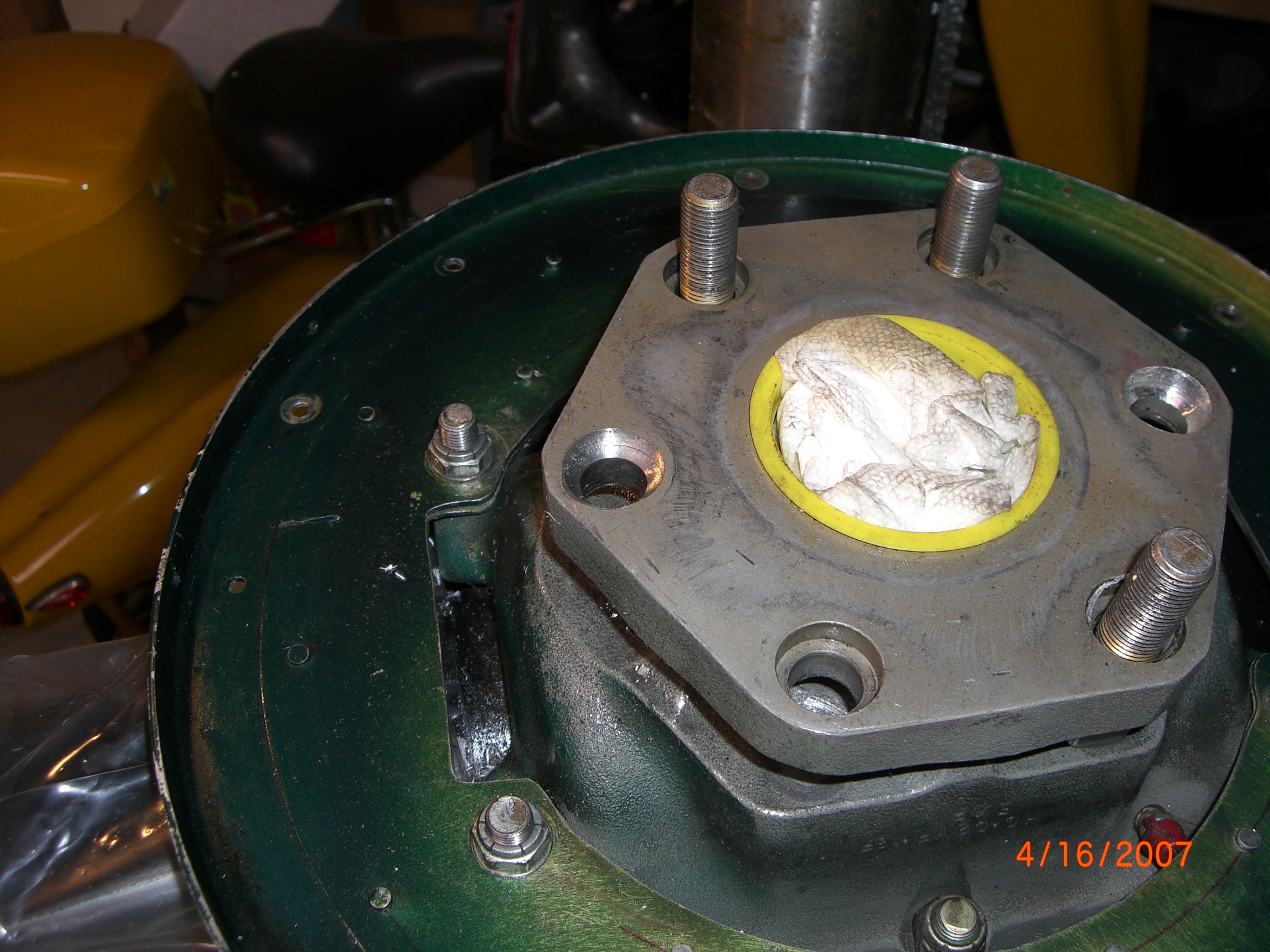
With this $40 bit in hand, we were easily able to make a nice counter bore hole to match the other ones. Now its time to Mount the prop and go fly. See the nice holes below.
I mounted the prop with the blades at the 9-3 position as Les suggested. I rolled her out of the hanger and began a dynamic balance. It was so darn windy, I could not get a good balance done. So I bagged it. Les also asked that I do a spectrum plot survey during my dynamic balance to capture that data also. Here it is.
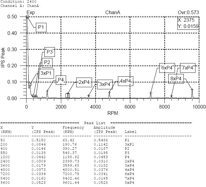
I went flying and again, ran at 23.3"MP, ~7k' and took readings at 2600, 2400, 2200 and 2000 RPM with the transducer mounted in both vertical and horizontal position. There was no question that during this flight, the vibration was nearly gone through about 2230rpm, then progressively worse to 2000rpm. Links to full data on the vertical and horizontal position. Below is a snapshot of the data at 2400rpm as a comparison to above. If you look at the 1/2 order harmonic, P4, you will see its now at .0442 IPS. WOW!. and 85% improvement. Amazing.
|
Engine RPM |
2000 |
2200 |
2400 |
2600 |
|
Peak IPS |
0.323 |
0.319 |
0.266 |
0.214 |
New 9-3 clocking, ½ order harmonic IPS
|
Engine RPM |
2000 |
2200 |
2400 |
2600 |
|
Peak IPS 1/2 order 9-3 clock |
0.3164 |
0.136 |
0.044 |
0.072 |
|
Percent improvement |
|
|
|
|
|
Normal Clock vs 9-3 |
2.0% |
57.4% |
83.5% |
66.4% |
So you can easily see that clocking the prop made a dramatic improvement. Its astonishing the difference in feel of the airplane. IMHO, there are a ton of planes that can benefit from this clocking change. Most folks just live with the vibration. Others go spend a ton of money to go for the MT 3 blade. I got it real smooth now and I am impressed with this effort and real data.
This was a lot of work to get to this point. Several prop swaps, cut hands on ring gears and safety wire. Blood on the floor. Long days. Lots of AvGas and time. But in the end, we have solved a problem.
Let me take a moment to thank 3 people who helped me. Doug Ripley for lending me his gismo to do real data captures. David Posey for taking a Sunday afternoon to help a friend with a problem.
And finally a special word of thanks Les Doud for his incredible customer service. In all my aviation time, I have NEVER had this level of service. I have emails a mile long from him where he takes the time to explain to me the various aspects of harmonics. He took the time to hold my hand through this process. He is a true engineer. Step by step we worked together in an effort to solve a problem. Solving problems is my life's work. His too. Im a problem solver at heart. With Les as a partner in this, we have really accomplished something. I can't thank him enough. Thanks Les. You a good man, a champion engineer, a model representative for Hartzell, and a now a friend. Now Hartzell can take this data and go do something. Maybe a new SB, maybe a new hub design. I dunno. Thats up to them. For me, I'm off to some smooth flying. Read this disclaimer
If you want the spreadsheet data on the captures on all the vib tests, both in flight and ground, Here it is. 2.6mb
Back to Super 8