The elevators (movable pieces in the tail that make the plane pitch up and down) are built just like the rudder with a forward spar, and skin stiffeners. They are rudders in disguise really. UNTIL you get to the left elevator and that darn trim tab thing. Then the fun begins.
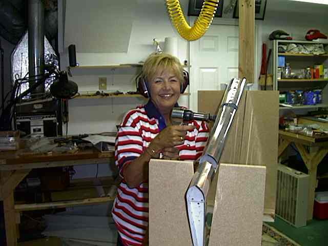
During my elevator building, I had several visitors to the shop. The first was Julie's mom Joyce. She was so fascinated with this plane building thing. Well you know what fascination means.... a helper. NEW RULE. Those who are fascinated get to be helpers. So she graciously volunteered to help with the riveting and dimpling. Have you ever seen a happier riveter in your life?
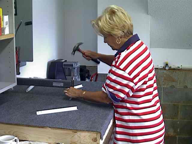
Of course there is lots of dimpling to do. Joyce found this to be a tedious and boring job. (No kidding I told her.) Here she is dimpling the stiffeners.
I also had some neighborhood kids stop by. They heard the noises of the pneumatic tools and just had to come check it out. These kids are 5 years old. A bit young for helping read the drawings, but not too young to play with stuff and otherwise provide for some entertainment. They just loved that air drill. I gave em a scrap piece of wood (no experimental playing on plane stuff) and off they went, drilling hole after hole. Laughing all the way as the drill went zing, zing zing. The air coming out of the bottom of the drill made their hair fly up. It was hysterical, and fun to watch them learn a new skill. They got to try the air riveter as well. Took four hands for them to operate. One kid holding the gun, the other holding the kid holding the gun. They thought that was a blast. As they squeezed the gun against a piece of wood, the gun would move all over the place. Anything w/i a 3foot radius was apt to get plunged with the rivet gun. What fun!!!

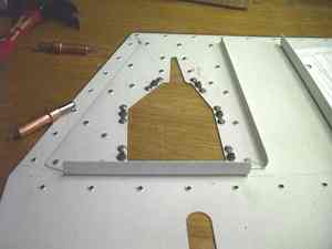
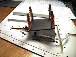
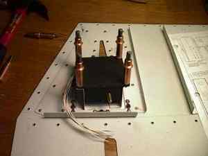
Now lets talk about the left elevator and the trim tab. I have opted for the electric trim mechanism offered by Van's. Van's made it very clear that this elevator trim area is the single most difficult item in the tail section and the one most makes are made on. And I can see why. The plans do show the unit, but the size of the diagram that is provided, and all that is going one around the trim mechanism makes it difficult to determine what goes where and in what order to tackle the problem. The instructions say "install electric trim servo if you have one" and that's it. Not very helpful. So here is a list of steps that will work.
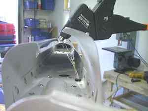
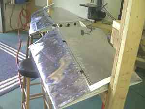
Skin bending on the forward leading edge is common on all tail surfaces. The technique is a simple one. Take a broom handle, or 3/4 PVC, and some duct tape and do some bending. Use a pipe wrench to grab the stick with and turn to give a smooth bend.
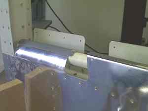
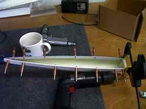
Putting on the tips, are the same for all tail surfaces with tips. Line the inside of the fiberglass with some thin aluminum so the rivets have something firm to grab. Use silicone between the aluminum and the fiberglass to hold it in place during drilling and setup. An end cap has to be fabricated out of some spare balsa wood or equivalent light weight product. Cleco's hold it together while silicone sets up. I'm just getting them ready for installation, Ill wait till near the end of the project to rivet them on so the "hanger rash" monster does not bang em up.
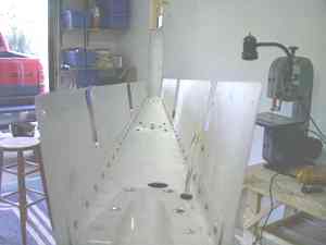
A real fun part is hanging the elevators on the horizontal stab for alignment. It's a point at which it kinda sorta looks like parts of a plane.
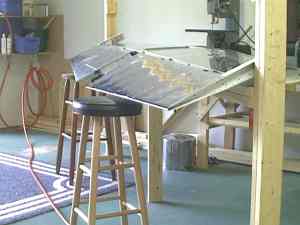
They are done!!
Last updated 11/05/02