It was exciting to begin one of the most challenging aspects of this project, the electrical system. Its challenging because there is very little direction from the plans and you are pretty much on your own. There are many web sites available to give you some helpful advice. But since everyone has different elements, it is all custom. That is half the fun. I would suggest Aeroelectrics download to get you started on the design.
There is a balancing act here of time, effort and money. You need to keep in mind that the engine will have to come out one day. So connectors to facilitate this are a must. Also there is considerable debate on the use of shielded vs. unshielded wire. I errored on the side of using shielded rather than not in most cases. Dealing with shielded is a pain in the butt, but I don't want to have to chase down radio noise later. Also I used Molex connectors from Radio Shack on most of my connectors. They are not cheap, but the quality is good.
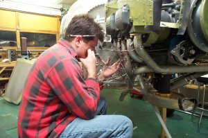
Here I sat studying (ok crying) over the mess that is created as bundles of wires come together.
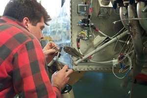
In all cases, I crimped, soldered, and heat shrinked all connectors for strength and reliability. A use of a torch (trigger activated) and vise grips as a heat sink to draw the heat away from the wire worked great and went pretty fast. Also my wire strippers are the type you squeeze and it strips and pulls off the insulation all in one whack and was very speedy when there are hundreds of wires to deal with.
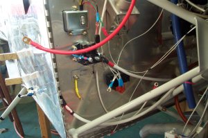
Here is a close-up of the lower right forward firewall. Top left is the adjustable voltage regulator, then starter solenoid, then the master relay (missing here cause I had to send mine back to Vans because it did not work). Center picture, black object with blue heat shrink and rtv sealant is the manifold pressure sensor for the engine monitoring system.
More to come as I make more progress.
Last up dated 11/05/2002